Guide
How 3D Scanning Helps Reverse Engineer Legacy Parts
A practical guide for Tamworth manufacturers using 3D scanning to capture legacy parts, rebuild CAD data, and plan replacement or redesign work.
A machine, assembly, tool, fixture, or spare component can remain useful long after its original engineering data has disappeared. The drawing may be missing, the CAD file may be in an obsolete system, or the physical part may no longer match the surviving paperwork. For manufacturers in Tamworth and nearby, 3D scanning can provide a practical starting point for understanding that geometry before a replacement or redesign is considered.
The important phrase is starting point. A scanner can record accessible surface geometry, but the project still needs a defined purpose and engineering review. A scan is not automatically a production-ready CAD model.
What 3D scanning captures
A 3D scanner observes the visible surface of an object from multiple positions. Those observations can be assembled into a point cloud: a large set of measured locations representing the captured surface. The points can then be connected and processed into a mesh, which describes the surface with many small faces.
That mesh can be useful for visualisation, comparison, reference, or further engineering work. It is not the same thing as an editable, dimensioned CAD model. Where the project requires CAD, someone must interpret the captured shape and decide how features such as planes, cylinders, holes, blends, patterns, and interfaces should be represented.
A released manufacturing definition goes further again. It may need critical dimensions, tolerances, datums, material, heat treatment, finish, inspection requirements, revision control, and approval. Captured geometry does not establish material, tolerance, function, or design intent.
Start with the required outcome
Scanning the part before agreeing the objective can create an impressive digital model that does not answer the manufacturing question. Begin by deciding what the result needs to support:
- documenting the current physical condition;
- creating reference geometry for a replacement;
- rebuilding editable CAD data;
- comparing a physical component with existing CAD;
- understanding a mating envelope or interface;
- redesigning a weak, obsolete, or difficult-to-manufacture feature.
The required output, review effort, and supporting measurements depend on that objective. A visual reference model and an approved definition for a safety-critical replacement are not interchangeable deliverables.
From physical part to an engineering decision
A controlled legacy-part project usually moves through seven stages.
1. Define the purpose
Agree whether the work is for documentation, replacement, redesign, comparison, or inspection. Identify who will review the result and what decision it must support.
2. Review the available evidence
Examine the part’s condition, size, access, visible and hidden features, mating components, and any drawings, CAD, photographs, manuals, or previous measurements. Record conflicts rather than silently choosing one source.
3. Capture accessible surfaces
Collect views from the positions needed to cover the relevant external geometry. Coverage matters because the digital result cannot describe a surface that was hidden from the capture method.
4. Align and clean the data
Combine the captured views and remove unrelated or clearly erroneous data. Produce a mesh or reference model suitable for the next agreed step while retaining traceability to the source capture.
5. Interpret geometry into CAD when required
Use the captured surface as evidence when rebuilding design features. This stage involves judgement: an as-scanned radius, worn bore, rough casting, or slightly distorted plane may not represent the intended nominal geometry.
6. Review engineering requirements separately
Confirm critical interfaces, dimensions, datums, tolerances, material, finish, function, manufacturing route, and inspection needs. Use drawings, mating parts, manual measurements, standards, or engineering analysis where scan data cannot answer the question.
7. Approve the resulting definition
The customer’s engineering and quality authorities should approve any replacement or redesign through their normal controls. The customer must also confirm that it has the right to reproduce the component before manufacturing work is released.
Where legacy-part scanning can help
3D scanning can be particularly useful when:
- a replacement is needed but no trustworthy model exists;
- the physical part differs from an old or incomplete drawing;
- cast, formed, organic, worn, or complex external geometry would be slow to describe manually;
- a mating envelope or interface needs to be understood;
- the component will be redesigned rather than copied blindly;
- baseline geometry is needed for documentation or later comparison.
It can also reduce the amount of geometry that must be recreated from a blank screen. The benefit is not that engineering judgement disappears. It is that the team has a richer geometric reference from which to make and document decisions.
Where scanning alone is insufficient
Hidden or inaccessible features may need other evidence or measurement methods. Internal passages, closed cavities, wall thickness, threads, and obscured interfaces cannot be assumed from an external surface model.
Scanning also does not automatically determine:
- material grade or condition;
- heat treatment or coating specification;
- tolerance, fit, or datum intent;
- required surface finish;
- loads, failure modes, or fitness for use;
- legal ownership or permission to reproduce the design.
Surface condition can affect the capture approach. Reflective, transparent, very dark, obstructed, damaged, or moving surfaces may require preparation, a different method, or supporting measurements. The correct response depends on the part and the required outcome, not a universal scanner setting.
Do not treat wear as design intent
Worn or damaged geometry deserves particular care. If a bore has opened up, a face has distorted, or an edge has broken away, reproducing the captured shape may reproduce the failure rather than the original component.
The review should distinguish between geometry that must be preserved, geometry that should be restored to an inferred nominal condition, and geometry that should be redesigned. Mating parts, functional requirements, surviving drawings, wear patterns, and conventional measurements may all contribute to that decision.
This is also why a polished mesh should not be mistaken for authority. Smoothing or filling missing data can improve a visual model while concealing uncertainty. Important repairs and assumptions should remain visible to the people approving the engineering definition.
On-site scanning or a supplied part
Some components can be transported and reviewed away from the machine or assembly. Others are too large, fragile, valuable, or difficult to remove, making a site discussion more appropriate. Triaxis can discuss scanning at a customer’s site or from a supplied part, subject to reviewing the access, condition, objective, and required engineering output.
Useful early information includes photographs, approximate overall size, the reason the data is needed, whether the part can be moved, any available drawing or CAD reference, known mating features, and the decision the final data must support. These details help define whether scanning is suitable and what additional engineering evidence may be needed.
For a broader view of the available support, see Triaxis’s 3D scanning and reverse-engineering services.
Turn the physical part into a controlled starting point
3D scanning can make complex legacy geometry easier to see, compare, and interpret. Its value is strongest when capture is connected to a clear objective, supporting evidence, engineering judgement, and an approval process.
The result should not be “a scan” with an uncertain purpose. It should be the right level of geometric evidence for the next controlled decision: document, compare, rebuild, redesign, or manufacture.
Discuss a legacy part or 3D scanning requirement.
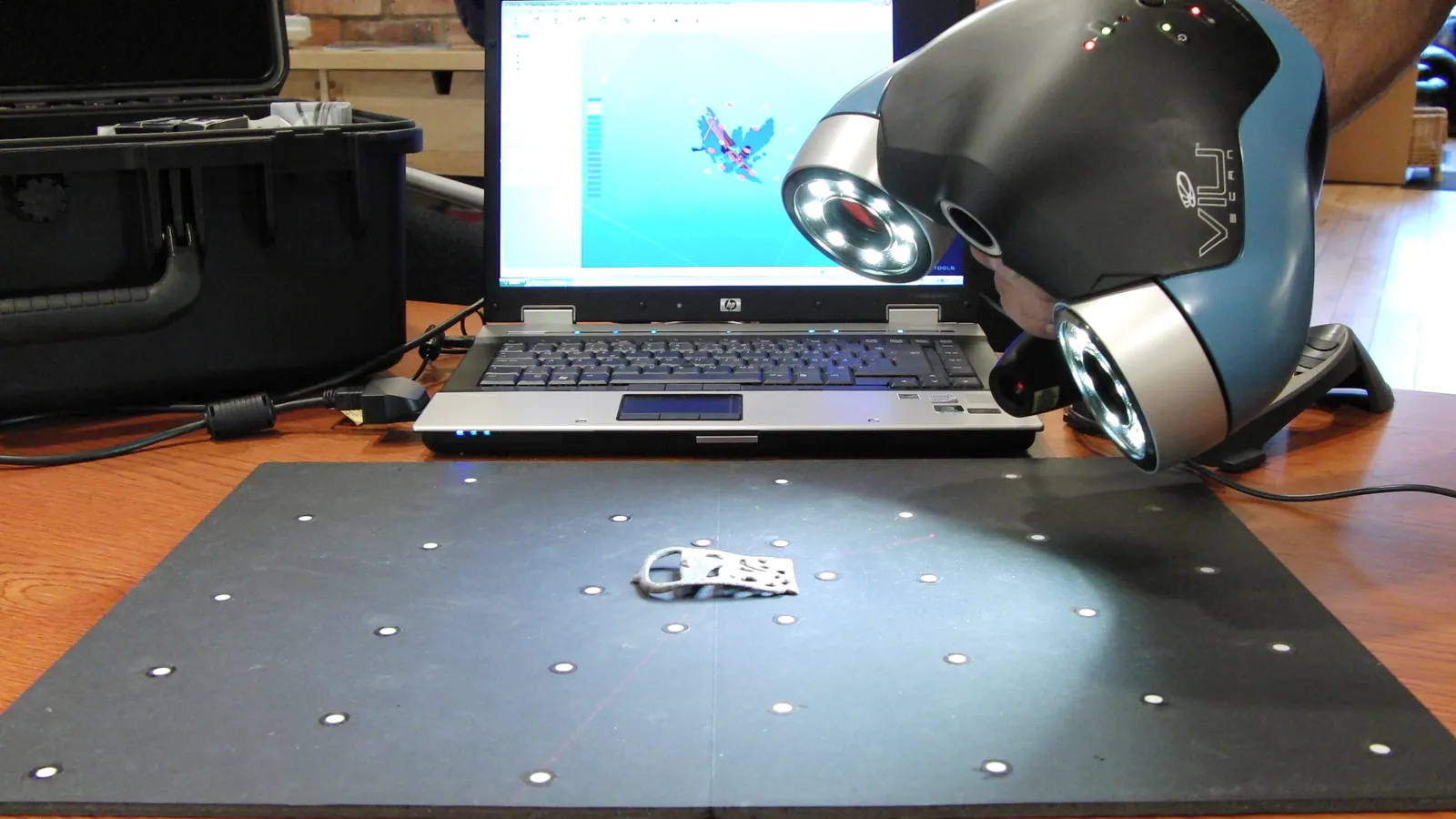
Cover image: Creative Tools via Wikimedia Commons, licensed under CC BY 2.0. Cropped and colour-adjusted. This is representative imagery and does not show Triaxis equipment, personnel, client work, or a promised workflow.
