Guide
3D Scanning vs Traditional Measurement for Reverse Engineering
Compare 3D scanning with calipers, micrometers, gauges, CMM evidence, drawings, and engineering review when reverse engineering an existing part.
Choosing between 3D scanning and traditional measurement is not really a contest between new and old technology. It is a question of evidence: what must be understood about the physical part, what decision will be made from the data, and which combination of methods can support that decision.
A scanner may capture thousands or millions of locations across a complex visible surface. A micrometer may provide one carefully controlled measurement across two contact points. A gauge may answer whether a feature passes a defined limit. A coordinate measuring machine may collect structured measurements of selected features against a planned alignment. Drawings, mating parts, material records, and engineering experience may explain facts that none of those measurements can establish alone.
For reverse engineering, the best answer is often a combined measurement plan rather than a single instrument.
Start with the engineering outcome
Before selecting a measurement method, define what the resulting information needs to support. Common outcomes include:
- documenting the current shape and condition of a component;
- creating reference geometry for an editable CAD model;
- reproducing a non-critical replacement part;
- redesigning a component while preserving important interfaces;
- comparing a physical part with existing CAD or drawings;
- investigating wear, distortion, damage, or an assembly problem.
These outcomes do not require the same evidence. A surface model used to understand packaging space is different from a released manufacturing definition containing controlled datums, dimensions, tolerances, material, finish, and inspection requirements.
The required outcome should determine the measurement plan. The availability of a scanner, CMM, or set of hand tools should not determine the outcome.
What 3D scanning contributes
3D scanning is useful when the shape itself contains a large amount of relevant information. Multiple views of accessible surfaces can be combined into a point cloud and then processed into a mesh. That mesh provides a dense digital representation of the observed external geometry.
This can be valuable for:
- freeform, cast, formed, sculpted, or blended surfaces;
- broad shape and envelope capture;
- recording geometry before a worn or damaged part changes further;
- comparing visible surfaces with a nominal CAD model;
- providing reference data from which CAD features can be interpreted;
- showing relationships that would require many isolated manual measurements.
Scanning does not automatically produce design intent. A mesh may show that a surface is slightly curved, a hole is worn, or a casting is irregular, but it does not decide whether the CAD model should preserve, repair, simplify, or idealise that geometry. It also does not automatically establish material, hidden features, tolerances, fits, or manufacturing requirements.
What traditional measurement contributes
Traditional measurement is a broad category. Each method answers a different kind of question.
Calipers and micrometers
Hand tools can be effective for accessible lengths, diameters, thicknesses, steps, and other defined features. They provide discrete measurements rather than a complete surface. Their usefulness depends on the feature, contact geometry, access, instrument condition, measurement method, and operator competence.
These tools are often valuable for checking critical sizes while a scan supplies the wider shape. They can also provide independent reference dimensions when captured data must be scaled, aligned, or interpreted.
Gauges and functional checks
Limit gauges, pins, thread gauges, templates, and mating components can answer practical acceptance or interface questions. A gauge may confirm that a feature satisfies an agreed limit without describing its complete geometry.
Functional evidence can be particularly important when the legacy part is worn. The captured surface describes the part as it exists; a controlled gauge, mating component, or interface requirement may help explain what the feature needs to do.
Coordinate measurement
A CMM or another planned coordinate-measurement process can collect structured data from selected features and relate them to an alignment or datum strategy. This can help evaluate planes, bores, positions, axes, and feature relationships where the required access and measurement strategy are available.
It should not be treated as a universal replacement for scanning. Sparse measurements may not describe a complex freeform surface efficiently, while dense scanning data may not provide the same controlled evidence for every critical feature. The correct choice depends on geometry, uncertainty, access, and the decision being supported.
Drawings, records, and mating parts
Measurement shows the physical item. Existing drawings may show nominal dimensions, tolerances, material, finish, revision history, and design intent. Mating parts can expose interfaces that are difficult to infer from one component in isolation. Maintenance records may explain wear or previous modification.
These sources can conflict. Reverse engineering should record those conflicts and resolve them deliberately rather than assuming that either the drawing or the existing part is automatically correct.
Method comparison
| Requirement | 3D scanning | Hand tools and gauges | Planned coordinate measurement | Drawings and functional evidence |
|---|---|---|---|---|
| Complex visible surfaces | Dense surface reference | Limited to selected sections or features | Depends on access and point strategy | May describe nominal intent if reliable |
| Critical discrete dimensions | Useful as reference, but may need confirmation | Direct evidence for suitable accessible features | Structured evidence for selected features | Defines requirements when controlled and current |
| Hidden or internal geometry | Not captured when inaccessible | Possible only where tools can reach | Possible only where probing or access permits | Sections, records, or other methods may be needed |
| Wear and damage | Records current visible condition | Quantifies selected worn features | Relates selected features to an alignment | Helps distinguish current condition from intended form |
| Editable CAD | Provides mesh or reference geometry | Supplies dimensions for feature construction | Supplies selected coordinates and feature relationships | Supplies nominal definitions and design context |
| Functional intent | Cannot establish it alone | Gauges and mating checks can add evidence | Measures geometry, not purpose | Engineering records and review remain essential |
The table is a planning guide, not a ranking of accuracy. No method is inherently correct for every part, feature, tolerance, or environment.
When scanning alone is not enough
Scanning needs support when the required answer depends on information outside the visible surface. Examples include:
- a bore, passage, thread, or cavity that cannot be observed;
- a critical fit that requires a defined measurement method;
- worn geometry that should not become the replacement definition;
- a datum structure that must represent how the part functions or is inspected;
- material, heat treatment, coating, or surface-finish requirements;
- a legal or commercial question about the right to reproduce the design.
Reflective, transparent, dark, obstructed, damaged, or moving surfaces can also affect the capture approach. That does not mean scanning is unsuitable, but it means the requirement and conditions need to be reviewed before promising an output.
A practical combined workflow
A combined reverse-engineering project can follow a controlled sequence.
- Define the purpose. State whether the work supports documentation, comparison, replacement, redesign, inspection, or another decision.
- Collect existing evidence. Gather the part, drawings, CAD, photographs, manuals, material information, mating components, and previous measurements.
- Identify critical features. Mark interfaces, datums, fits, clearances, mounting locations, and functional surfaces that require specific review.
- Plan the capture. Decide which visible geometry benefits from scanning and which dimensions or features need contact measurement, gauges, coordinate measurement, or another method.
- Capture and check coverage. Record the relevant accessible surfaces and retain evidence of gaps or uncertain areas.
- Measure selected features. Use suitable independent methods for the critical features identified in the plan.
- Build and review CAD. Interpret the combined evidence rather than tracing every imperfection into the model.
- Define manufacturing requirements. Add controlled dimensions, tolerances, material, finish, inspection, and revision information through engineering review.
- Approve the result. The customer’s engineering and quality authorities should approve any replacement or redesign and confirm the right to reproduce it.
This process keeps a useful distinction between observed geometry, interpreted CAD, and an approved manufacturing definition.
Questions to answer before choosing a method
Useful early questions include:
- What decision must the data support?
- Is the objective to reproduce the current part or recover its likely intended form?
- Which features are critical to fit, function, safety, or inspection?
- Are important surfaces visible and accessible?
- Is the part worn, damaged, coated, reflective, flexible, or difficult to move?
- Are drawings, CAD, mating parts, gauges, or material records available?
- Does the result need to be a mesh, reference model, editable CAD model, inspection comparison, or released drawing?
- Who will review and approve assumptions about nominal geometry and design intent?
Clear answers help prevent unnecessary capture and reduce the risk of producing detailed data that cannot support the required engineering decision.
Choose evidence, not a favourite tool
3D scanning is strong at capturing complex visible shape. Conventional tools, gauges, and coordinate measurement can provide focused evidence for selected dimensions and relationships. Drawings, mating parts, and engineering review provide context that geometry alone cannot supply.
Used together, these methods can turn an existing component into a controlled starting point for documentation, CAD reconstruction, comparison, or redesign. Used without a defined outcome, any of them can produce measurements that are technically impressive but commercially unhelpful.
For the earlier stage of deciding whether an existing component is suitable for capture, read how 3D scanning helps reverse engineer legacy parts. You can also review Triaxis’s 3D scanning and reverse-engineering services.
Discuss a reverse-engineering measurement requirement.
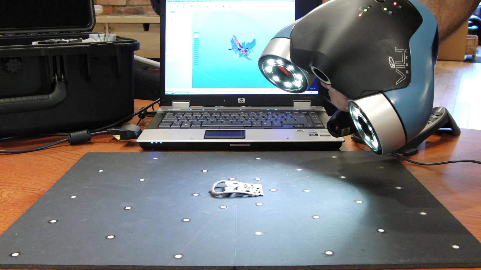
Cover image: Creative Tools via Wikimedia Commons, licensed under CC BY 2.0. Cropped and colour-adjusted. This is representative imagery and does not show Triaxis equipment, personnel, client work, or a promised workflow.
